The Navigation Display
You might be familiar with most of what's on screen but if not, lets go through it.
Navigation points
The built-in database of FIX, VOR, NDB and Airports places each waypoint in its relative position around you. If you move, they move too. In addition to these, the display will also show you user saved custom waypoints (CWP). These might be enough for flying but we thought that sometimes it might be interesting to know which localities are around you, especially if you are, say, driving a car. So for this we've introduced localities, a database of over 100k places worldwide; they are represented as waypoints and their name is formed by the first 6 characters of their names, so London is LONDON and New York is NEWYOR. The bottom keywords LOC, CWP, WPT, APT, NDB and VOR represent the status of the displaying of each type of waypoint. Click on them once and you enable them, click again and you disable them. LOC stands for localities and will display the real cities and towns around you.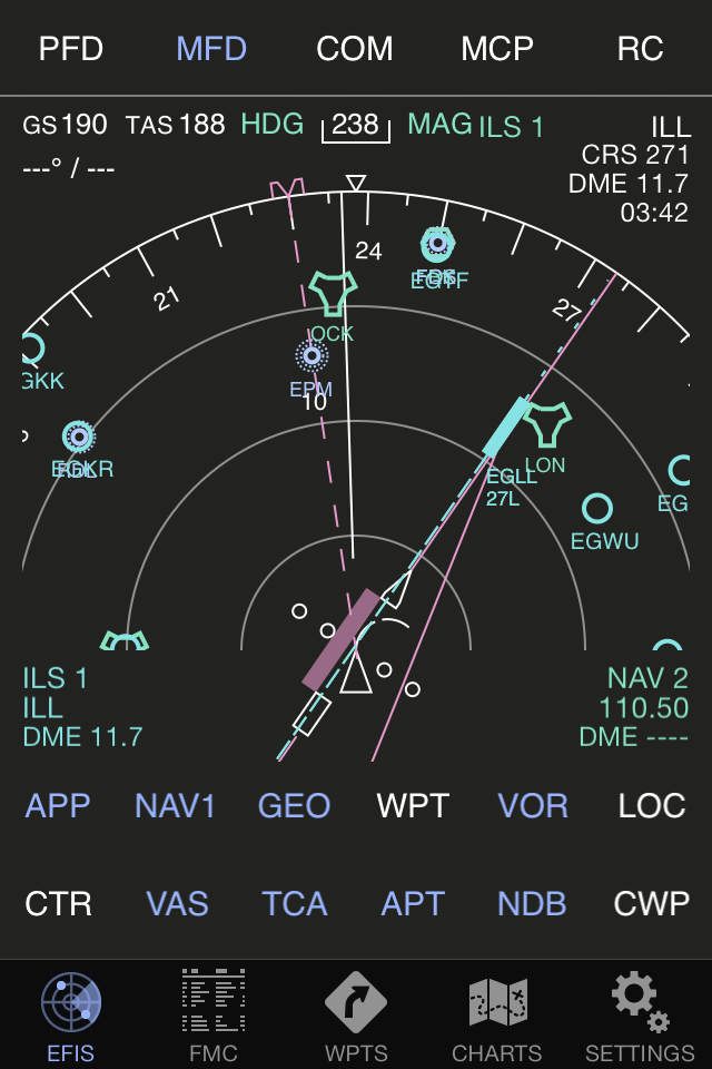
Display Modes
Tapping on the mode keyword (APP, VOR, MAP or PLN) will toggle the display mode. MAP will show the current position with heading facing up. APP will show the same with ILS approach aids if available and VOR the corresponding helpers. The APP, VOR and MAP modes can be displayed in either center (CTR) or expanded (EXP) views. MAP mode shows you TRK, the direction the aircraft is flying, whereas APP and VOR modes show the heading. The message EFIS MODE / NAV FREQ DISAGREE appears if you are in APP mode and have a VOR tuned in or if you are in VOR mode and have a localizer tuned in, much like on a real Boeing aircraft. PLN stands for plan mode and it naturally goes together with route plans; you need a route loaded into the FMC in order to make use of the full views. Plan mode is always displayed in center mode with the real north up. If you have a flight plan loaded, the next waypoint will be in the center and your aircaft will be drawn as it stands. The blue track shows the travelled path. If auto-pilot heading hold is engaged a magenta needle is also displayed in APP, VOR and MAP modes. Finally, a sequence of purple and white lines shows connected waypoints in accordance to your route plan.TCA mode
The Traffic Collision Avoidance mode will display aircrafts around you. This mode is currently available if you select VATSIM as an Air Traffic source under settings, in which case it will show everyone around you that is currently flying on the VATSIM network.
Radio Guidance
The frequencies dialed in the 1 and 2 radios are displayed in the lower left and right corners. When a navaid is captured (i.e. is in range) these will translate to their names. You can tune in and capture VORs, NDBs and Localizers. The VAS button allows you to swap between VOR and ADF mode, thus taking into account NAV or ADF radios.If there are DMEs colocated with captured navaids, the distance to them is also displayed.
APP mode
When you're approaching an airport the MFD will give you some guidance towards the runway with the aid of localization needles as the ones displayed on the screenshot. You can use one of three modes: NAV1, NAV2 or FMC.When in NAV1, the frequency dialed into NAV1 will be used to detect a localizer near you. You need to be in range of the localizer, which is to say, not higher than 4500 feet above its ground altitude and within a 30+30 degree each side cone when within 10nm or 10+10 degrees cone when further than 10nm up to its range.
When all these conditions are met the OBS needle will be auto-adjusted to the correct course and the approach magenta needle will move. Make them match and you are inline for an ILS landing.
NAV2 mode is similar to NAV1, only that it uses the second radio frequency.
FMC mode does not use either NAV1 nor NAV2 but instead the next waypoint entered in the FMC. So in order to make an ILS approach you need to enter the ILS localizer as the next waypoint of the FMC. Range restrictions do not apply on FMC mode.
VOR mode
VOR mode is similar to APP but requires the radial to be set in OBS/CRS and the VOR frequency to be tuned in NAV1/2.
TOC/TOD Arc
When climbing or descending, a green arc will appear in APP, VOR and MAP modes, showing the point at which the dialed target altitude will be reached.
The Snake
The snake, shown in APP, VOR and MAP mode, represents the rate of turn and where you will be in 30, 60 and 90 seconds at the current rate.
Zooming in, zooming out
You can zoom in and zoom out using multi-touch finger gestures on the screen (two fingers approaching or spreading out). The minimum supported is 1 nautical mile per full radius (so 0.25 nm per circle) which is only useful when you are moving slowly. The maximum is 640 nautical miles. Want to see it in terms of kms or miles? No problem, just change the distance units under Settings. Now every so often in wide range scales you might end up with too many waypoints on the screen; so many that it is both impossible to recognize anything and that it takes too long to draw them all in reasonable time (all points are calculated and drawn at regular intervals). So what happens then? You get an EXCESS DATA message just like in a real MFD and in this case the app automatically decreases the selected range.Remote Simulator Interaction
When using a simulator such as X-Plane, changing the range, displayed waypoints or mode will send the changes back to the simulator. Changing them on the simulator will likewise reflect these on AirTrack.
Heading
You can select magnetic or real under settings if your data source supports it. The current heading is displayed on top of the APP and VOR modes. If you have the auto-pilot heading hold engaged, a magenta needle will turn up showing the dialed heading until this one is in sync with the current heading.Speed and Winds
On the top left corner you will find (if available) information about the ground speed, the true air speed, the winds direction and the winds speed. Speeds are in knots unless changed to km/h or mi/h under settings. TAS is only displayed above 100 knots. The wind arrow gives you the direction of the wind with regards to your heading. So if the arrow points down it means the winds are against you and if the arrow points sideways you have cross-winds.Winds are not displayed if below 4 knots and are then only displayed again if above 6 knots.
Next Waypoint
This option will only be displayed if you have a flight plan loaded under the route planner. If so, it will show the name of the next waypoint, the estimated time of arrival at that same waypoint and the distance to it, all this on the top right corner of the display.GEO Mode
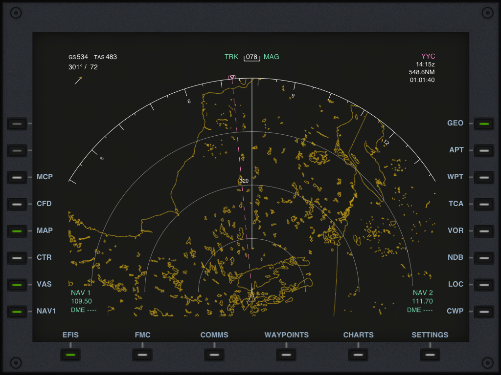
The GEO switch allows the display of the world's border and coast line contours as a background image to the ND. The contours are displayed in orange. The whole world is included.
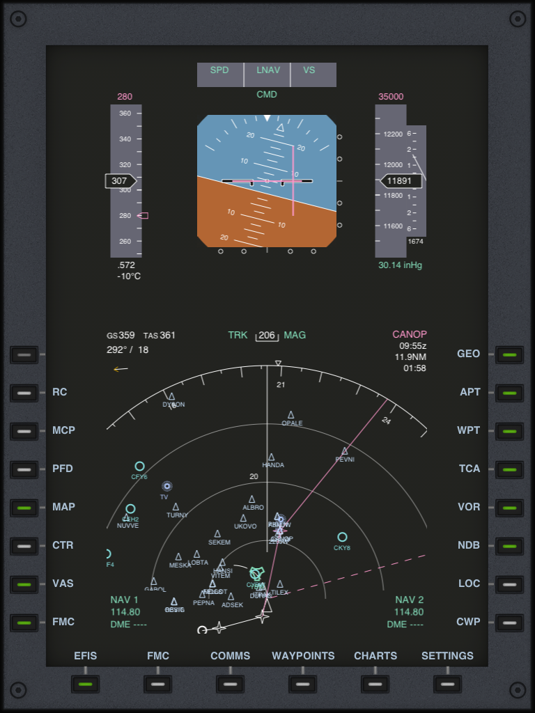
On the iPad
The iPad is a great device for flight simulation due to its large screen size. We built the MFD and the PFD in a single EFIS section of the AirTrack much like they can be found in real aircraft where these go together. The following screenshot illustrates these as seen on the iPad:
PFD and MFD mode only on iPad
You may also select a PFD only or an MFD only on the iPad, thus making use of the full screen for one of these; just click on the EFIS button or in the PFD/MFD/CFD button to toggle between modes. The screenshot below illustrates an MFD only in landscape mode.